![]()
公開日 2020年9月26日 最終更新日 2026年4月19日 by JE2UFF_Toshi
従来、主に使用していた720×8は水平偏波のため、ファラデーローテーション対策の一つとして、垂直偏波のアンテナが必要になりました。
Since 720×8, which was mainly used in the past, is horizontally polarized, a vertically polarized antenna is required as one of the measures against Faraday rotation.
最初は同じ720を4パラで使用しておりましたが、EMEの正解では有名なDG7YBNデザインのアンテナを作製してみようと考え、今回Phase-1とPhase-2に分けて製作を行ったのでその状況を紹介します。
At first, I used the same 720 with 4 paras, but I thought about making an antenna with the famous DG7YBN design in the correct answer of EME, so this time I made it separately for Phase-1 and Phase-2. I will introduce the situation.
DG7YBNのGTV70-11Wは、DL7APVが作成した128八木に使用されているアンテナとして有名です。
DG7YBN’s GTV70-11W is famous as the antenna used for 128 Yagi created by DL7APV.

Phase-1では最初の4パラを作成、Phase-2で更に4パラを追加して4パラ2段に発展させたものです。その際にはアンテナを取り付けるマストまで自製しました。
In Phase-1, the first 4 paras were created, and in Phase-2, 4 paras were added and developed into 4 paras and 2 stages. In that case, I made my own mast to attach the antenna.
Phase-1 GT V70-11W 4パラ製作
給電用のバランと、ラジエータ用のブラケットをアクリル板で作成した。
The balun for power supply and the bracket for the radiator were made of acrylic plate.
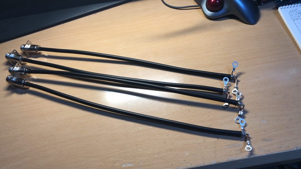
3/4λの給電部を4つ作成し、先端部分をこの後シリコンで固めて防水処理を実施。
Created four 3/4λ feeding parts, and then hardened the tip with silicon for waterproofing.
使用した同軸ケーブルは5D-FB-LITEを使用しているので、短縮率は80%で計算しました。
Since the coaxial cable used is 5D-FB-LITE, the shortening rate was calculated at 80%.
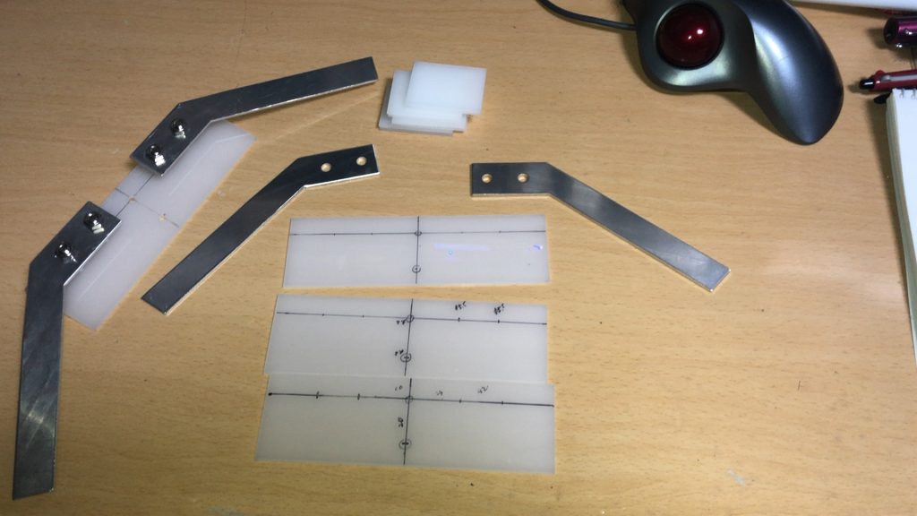
アクリル板を加工して、ラジエータ部分のブラケットを設計。この後穴を開けてラジエータを作成することになります。
The bracket of the radiator part is designed by processing the acrylic plate. After this, you will need to make a hole and create a radiator.
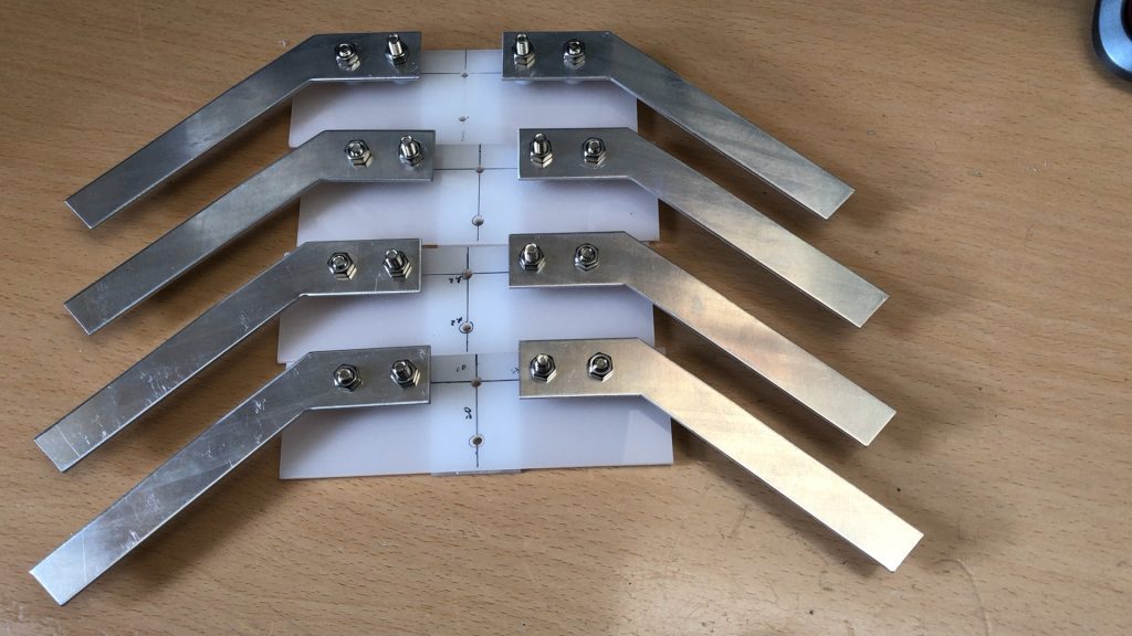
穴あけ作業を実施し、ラジエータを作成した。4つ並ぶと蟹のようにも見える。
Drilling work was carried out and a radiator was created. When four are lined up, it looks like a crab.
そして、一番めんどくさいと思っていたエレメントの作成を実施。ブームの上に取り付ける方法からブーム貫通型に変えたので、寸法が変更になり作り直し。
Then, I created the element that I thought was the most annoying. Since the method of mounting on the boom was changed to the boom penetration type, the dimensions were changed and it was remade.
最初から寸法を定めて削っていったので、1本にかなりの時間を必要としました。
It took a lot of time for one because I had to determine the dimensions and cut it from the beginning.
エレメントも天野アルミニウムさんから購入したアルミの無垢棒で再生策を実施。
The element is also regenerated with a solid aluminum rod purchased from Amano Aluminum.
これですべてのエレメントの準備が整いましたので、いよいよアンテナ本体の製作に入ります。
Now that all the elements are ready, it’s time to start making the antenna body.
こちらは全て部材も届いており、下準備は完了しているのでブームの穴あけ工事からになります。
All the parts have arrived here, and the preparations have been completed, so it will be from the boom drilling work.
とりあえず今回作成するのはGTV70-11wと言うタイプの物。あのDL7APVが使用している128八木と同じものなんです。
For the time being, this time I will create a type called GTV70-11w. It’s the same as the 128 Yagi used by that DL7APV.
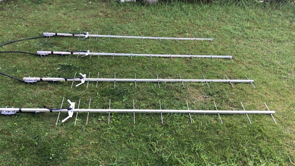
単なる11エレですが、ブームは2mを超えるワイドスペース八木になります。エレメントを固定するのは、DG7YBNオリジナルのエレメントストッパーを使用します。
It’s just 11 elements, but the boom is a wide space Yagi that exceeds 2m. To fix the element, use the DG7YBN original element stopper.
このためにYBNは海外発送しないという事だったので、DL7APVにお願いして代理購入してもらいDL7APVから送ってもらいました。
For this reason, YBN was not shipped overseas, so I asked DL7APV to purchase it on my behalf and send it from DL7APV.
これはブームの押し込むときにエレメントを挟み込み固定するタイプで、組み立ても非常に簡単です。
This is a type that sandwiches and fixes the element when pushing the boom, and it is very easy to assemble.
放射器を取り付ける前の10エレ状態。20㎜角で2.5mの角パイプを使用しております。いつもの天野アルミニウムさんからの購入で、板厚も2㎜程度有りかなりの強度は有ります。
10 elements before installing the radiator. We use a 20 mm square 2.5 m square pipe. It is purchased from the usual Amano Aluminum, and the plate thickness is about 2 mm, which is quite strong.
そして放射器を取り付けます。
Then install the radiator.
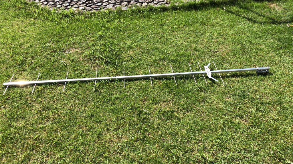
放射器を取り付けて完成形になりました。特徴は、ブーメランの形をしたダイポールが独特の形状なんです。この状態でバランを付けて、全アンテナSWRを432.1MHzで測定すると1.1~1.2と非常に良好でした。
The radiator was attached and it was completed. The feature is that the boomerang-shaped dipole has a unique shape. With a balun attached in this state, the SWR of all antennas was measured at 432.1MHz, which was very good at 1.1 to 1.2.
最後に、マストクランプで固定するに当たり角のままではつぶれてしまいそうな気がしたので、外回りに丸いアルミパイプを付けて完成となりました。
Finally, when fixing with the mast clamp, I felt that it would be crushed if the angle was left as it was, so I attached a round aluminum pipe around the outside to complete it.
ここまで完成したら、後は各アンテナの放射器に同軸バランを取り付けて完了になります。
Once completed so far, the coaxial balun is attached to the radiator of each antenna to complete the process.
これらを現状の720×8の間のメインブームに取り付けて4パラの構成にしました。
I attached these to the main boom between the current 720×8 and made it a 4-para configuration.
ゲインとしては、11エレなので15dBi程度しかありませんが、4パラで21㏈iくらいにはなりますのでちょっと高めのLNAを付ければ何とか受信は可能かと思います。
Since the gain is 11 elements, it is only about 15 dBi, but it will be about 21 ㏈ i with 4 paras, so I think that it can be received somehow if a slightly higher LNA is attached.
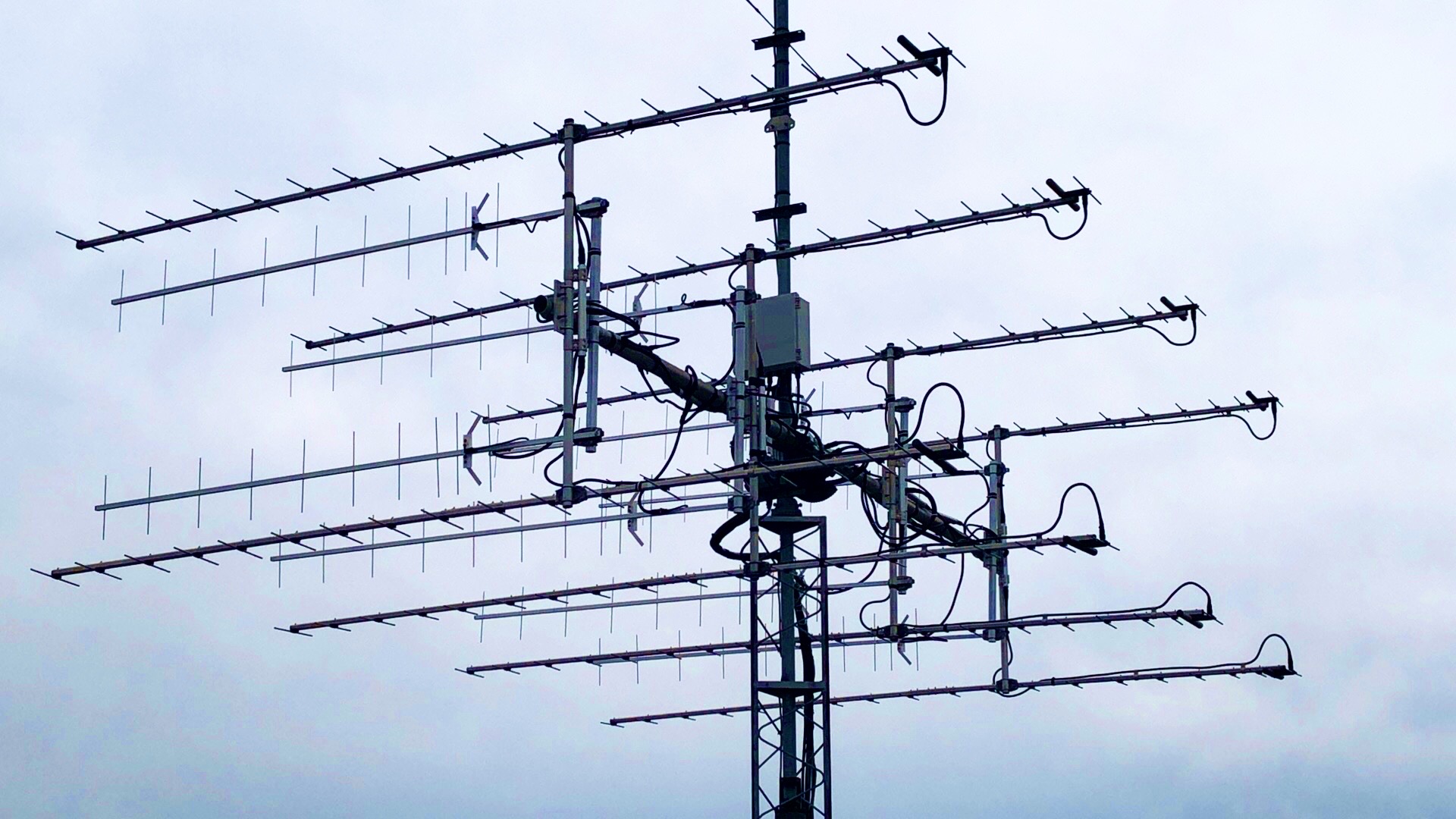
下記の写真が取付完了した状態です。水平偏波の間にある垂直偏波が今回作成したアンテナです。
The picture below shows the completed installation. The vertically polarized wave between the horizontally polarized waves is the antenna created this time.
今までとは違う八木なのでちょっと楽しみですね。
It’s a different Yagi than before, so I’m looking forward to it.
このアンテナは、DG7YBNのトップページのスライドショーの部分と、GTV70-11Wのページです。しかも、あのDL7APVの128八木アンテナの写真の上にのせていただいております。
This antenna is the slide show part of the top page of DG7YBN and the page of GTV70-11W. Moreover, it is placed on the photo of the 128 Yagi antenna of that DL7APV.

Phase-2 GT V70-11W 4パラx2の製作
いよいよ残りの4パラを作成するために
Finally to create the remaining 4 paras
GTV70-11のエレメント作成を実施
必要な工具としては
1.曲尺
2.万力
3.ワイヤーカッター
4.グラインダー
の4つくらいで特殊なものは必要ありません。まずはΦ4のアルミ無垢棒を凡そリフレクター~D5までは350㎜~310㎜までの間でカットします。それ以下D6~D9までは300㎜でカットして、正確な目的のサイズにしるしをつけて、その近くてワイヤーカッターを用いてカットします。
As a necessary tool
1. 1. Steel square
2. vise
3. 3. Wire cutter
4. grinder
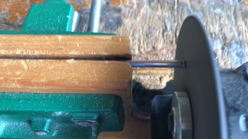
You don’t need any special ones. First of all, cut a solid aluminum rod of Φ4 from the reflector to D5 from 350 mm to 310 mm. Cut from D6 to D9 below that with 300 mm, mark it to the exact desired size, and cut it near it using a wire cutter.
ワイヤーカットで目印近くをカットすることで、削る量を極力減らします。
By cutting near the mark with a wire cut, the amount of scraping is reduced as much as possible.
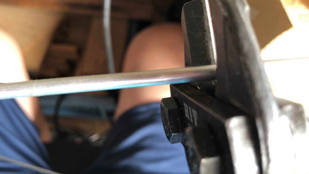
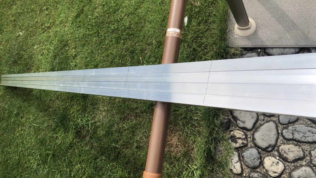
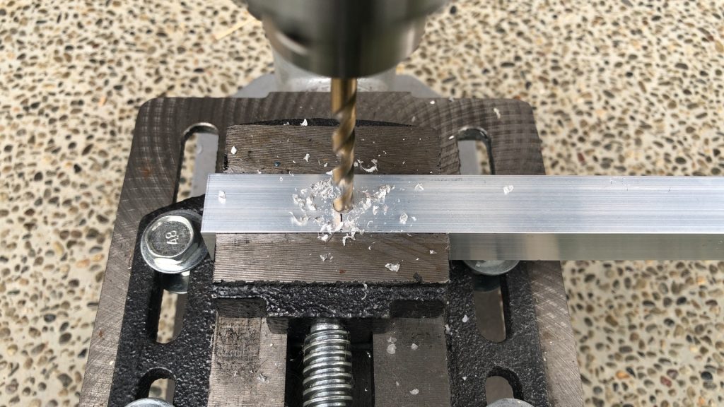
次に、凡その長さになったアルミ無垢棒を万力にセットして、所定の長さになるようにグラインダーで削っていきます。
Next, set a solid aluminum rod of approximately length to a vise and grind it to the specified length with a grinder.
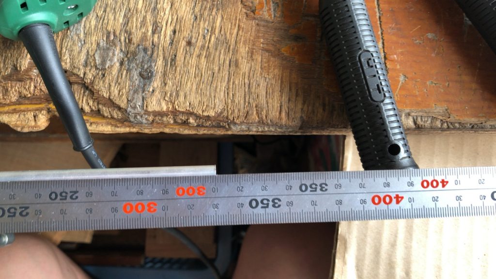
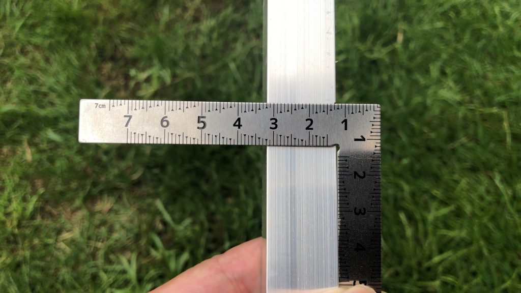
ハンドグラインダーのために、切削面が斜めになりやすいのでおおよその長さまで削ったら、最後はまっすぐになるように削って最終寸法を曲尺を用いて寸法測定します。
Because of the hand grinder, the cutting surface tends to be slanted, so after cutting to the approximate length, cut it so that it is straight at the end, and measure the final dimensions using a steel square.
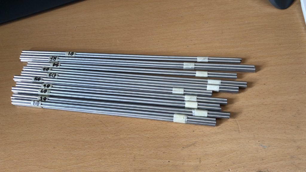
この地道な作業を、RF、D1~D9までの全部で10種類を製作アンテナ本数分作成します。
We will create a total of 10 types of RF, D1 to D9 for the number of manufactured antennas.
今回は、すでに作った4パラを2段にするためもう4本作製するので書くエレメントを4本ずつ作成しました。
This time, I will make 4 more elements to make the 4 paras that I have already made into 2 stages, so I made 4 elements each.
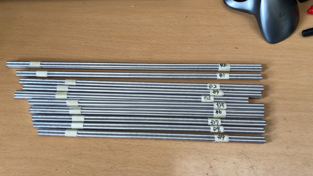
購入サイズが2500㎜なので、それを凡その長さでバンバンカットしてから最終寸法まで削り上げるのに、大体2時間程度で作成できました。
Since the purchase size is 2500 mm, it took about 2 hours to cut it to the final size after cutting it to an approximate length.
必要本数の40本を最初に切り出してしまえば、後はそんなに大変な作業ではないですね。
If you cut out the required number of 40 pieces first, the rest is not that hard work.
天野アルミニウムさんから購入するアルミの無垢棒は、結構強度が有るので取り扱いが非常に楽です。※グラインダーで削っても歪まないですね。精度もバッチリ!
The solid aluminum rods purchased from Amano Aluminum are quite strong and easy to handle. * It will not be distorted even if it is ground with a grinder. The accuracy is perfect!
これで放射器以外のエレメントは全て完成しました。
This completes all the elements except the radiator.
さて、GTV70-11Wですがエレメントの製作までは完了しておりますが、肝となる放射器の部分の政策に入ります。エレメントがブーメランのようになっていることが特徴なんですよね。EUでは自作アンテナとしては非常にポピュラーになりつつあります。
By the way, GTV70-11W has completed the production of the element, but we will enter the policy of the essential radiator part. The feature is that the element is like a boomerang. It is becoming very popular as a self-made antenna in the EU.
かのDL7APVはこのGTV70-11Wを128本接続しているビッグアンテナですからね。
That DL7APV is a big antenna that connects 128 GTV70-11Ws.
まず材料で絶縁体の材料となるのは2㎜厚のアクリル板が到着したので制作に入ります。
First of all, the material for the insulator is a 2 mm thick acrylic plate, so we will start production.
放射器の作成
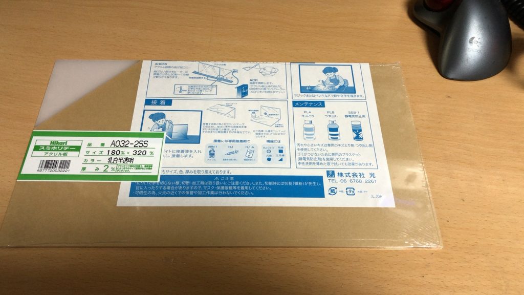
Amazonから購入した180×330の白色のものです。まずこれを40㎜幅で切っていきます。
It is a 180 x 330 white one purchased from Amazon. First, cut this into 40 mm width.
マーキングして切り出していきます。アクリル板なので、L型のキバンカッターを使うと、V溝を切り込んだ後に力を入れれば綺麗に割れるので非常に便利です。
I will mark and cut out. Since it is an acrylic plate, it is very convenient to use an L-shaped Kiban cutter because it will crack cleanly if you apply force after cutting the V groove.
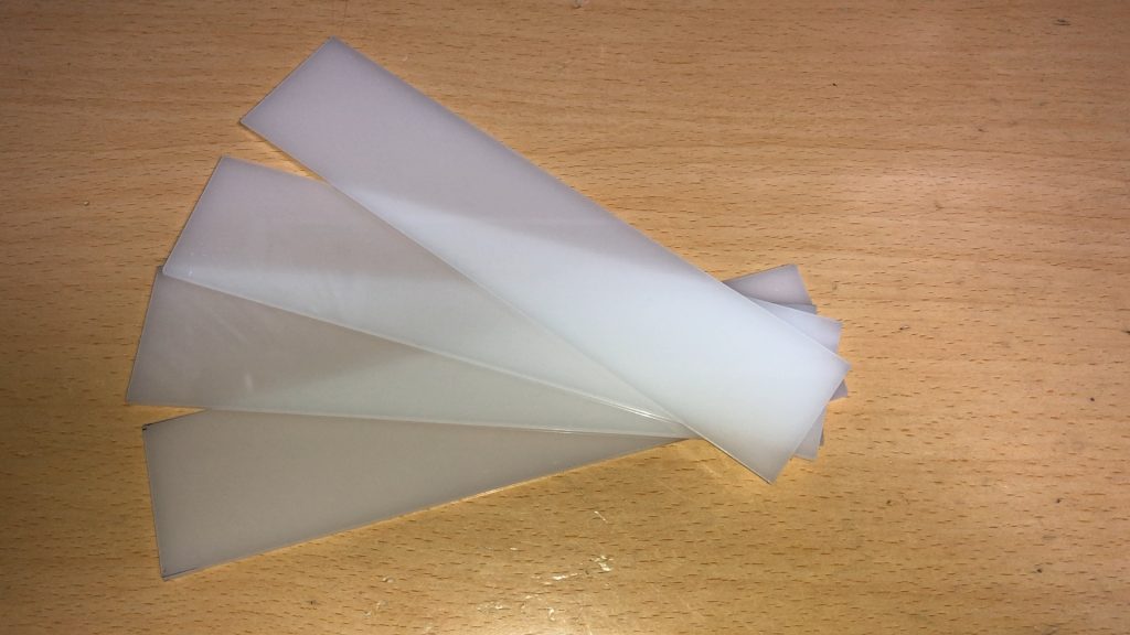
この40㎜x180㎜の1枚が1つの放射器用絶縁体になるんです。ここから、穴をあける位置のマーキングと、V型形状にするかっと線を入れていきます。
One piece of this 40 mm x 180 mm becomes one insulator for the radiator. From here, mark the position to make a hole and add a V-shaped bracket line.
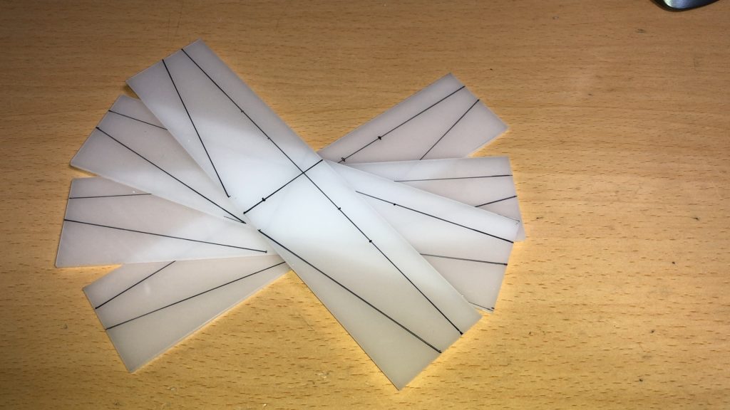
こんな感じでマーキングを完了したら、まずは斜めの線を同じようにカットしていきます。ここでもキバンカッターで切れ込みを入れ、折る形の方法をとります。
After completing the marking like this, first cut the diagonal line in the same way. Again, use a Kiban cutter to make a notch and fold it.
鋭角部分は若干部材が残りますが、気にせずバンバンカットしていきます。
Some parts will remain at the acute angle part, but we will cut it without worrying about it.
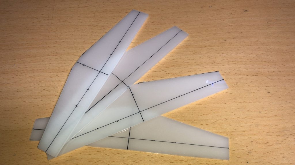
ここまで出来たら、後は穴をあければ絶縁部品は完了です。エレメント用はΦ5.5で4ヶ所穴をあけ、ブーム取付用はΦ3.2で2ヶ所穴をあけます。
Once this is done, all you have to do is make a hole and the insulation is complete. For the element, make 4 holes with Φ5.5, and for the boom mounting, make 2 holes with Φ3.2.
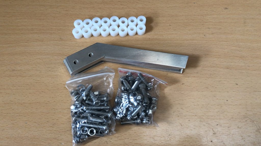
最終組み立てに使用する部品は、アルミ板のエレメント、ナイロンスペーサー、SUSのネジになります。
The parts used for final assembly are aluminum plate elements, nylon spacers, and SUS screws.
アルミのブーメラン形状をしたエレメント部分は、自分でCADで図面を書いて、それを元に知り合いに作ってもらいました。同軸のコネクタ固定ブラケットも同じですね。両方とも市販品ではありません。
For the boomerang-shaped aluminum element part, I wrote a drawing by myself with CAD and asked an acquaintance to make it based on it. The same applies to the coaxial connector fixing bracket. Both are not commercially available.
これらの部品を、先に作った絶縁版に取り付けていきます。
We will attach these parts to the insulation plate we made earlier.
後はネジ締めだけですので、すぐに完了しますね。
All you have to do is tighten the screws, so it will be completed immediately.
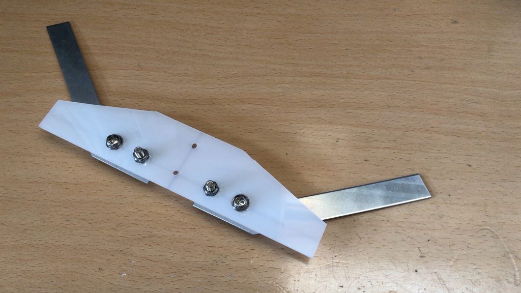
これが出来上がった放射器です。ネジは振動での緩みを警戒し、強く締め付けた後に接着剤で固定します。後はこれに同軸バランを取り付ければ完成になりますね。
This is the finished radiator. Be wary of loosening due to vibration, and tighten the screws tightly before fixing them with adhesive. After that, if you attach a coaxial balun to this, it will be completed.
まずはこの放射器を4セットまで作ります。
First, make up to 4 sets of this radiator.
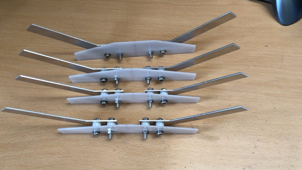
このような感じで、同じユニットが4つ出来上がりました。
With this feeling, 4 of the same units were completed.
出来上がったユニットに対して、防水対策としてテナーコートを塗布し、エレメントの表面とネジの表面をコーティングします。
A tenor coat is applied to the finished unit as a waterproof measure to coat the surface of the element and the surface of the screw.
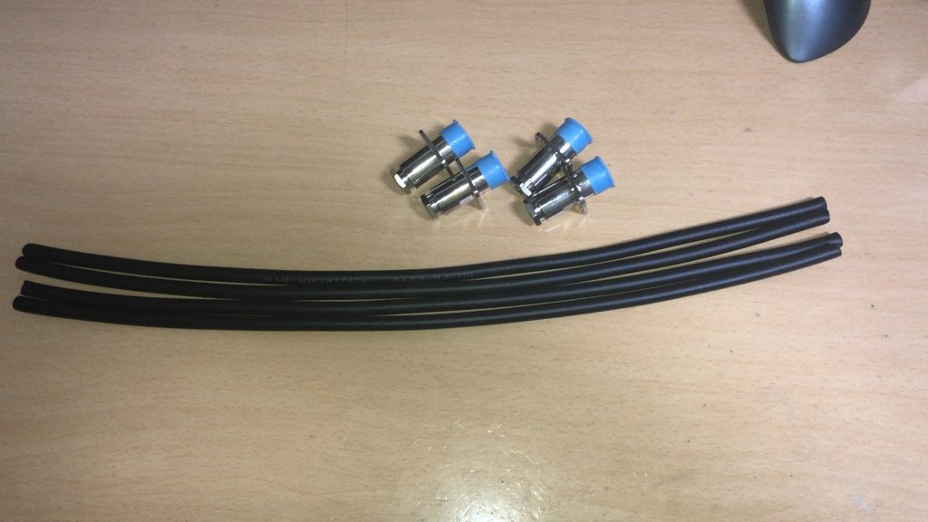
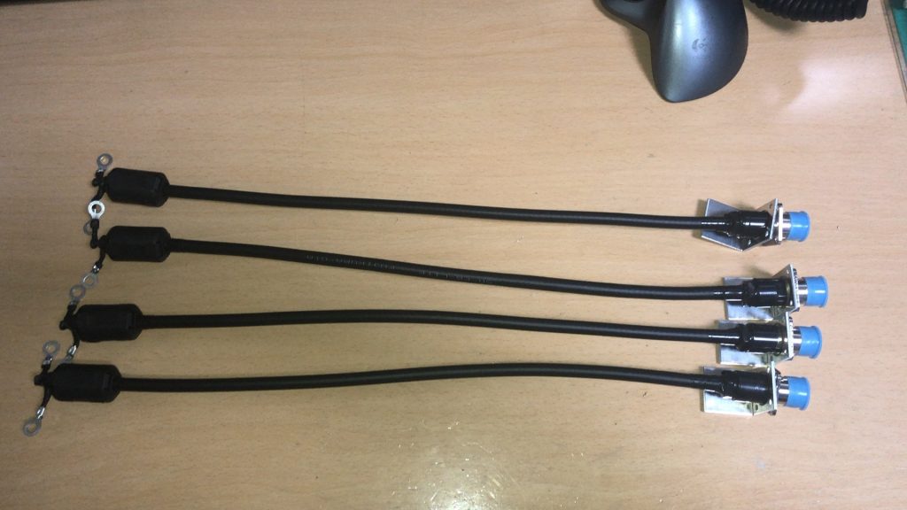
給電部に使う同軸バランの作成
まずはベースとなる5D-FB-LITEを3/4λの長さに切断します。この同軸の片側にコネクタ、片側に給電部に接続する端子を取り付けます。
First, cut the base 5D-FB-LITE to a length of 3/4λ. Attach the connector to one side of this coaxial and the terminal to connect to the power supply on one side.
この同軸コネクタが、日本ではなかなか見つけることができなく、いつも購入する秋月や千石では売っていないので、今回もまたebay経由で深センから直接購入しました。最近はコロナの影響もだいぶ収まったようで、1週間程度で到着しました。
This coaxial connector is hard to find in Japan and is not sold in Akizuki or Sengoku, which I always buy, so I bought it directly from Shenzhen via ebay this time as well. Recently, the influence of COVID-19 seems to have subsided, and I arrived in about a week.
まずは4本の同軸すべて、同じ長さに被覆を剥いてコネクタから中身を出し挿入する部品と半田付けする部品を取り付けます。同軸ケーブルの線系にばらつきがあるのか、コネクタのナット部にばらつきがあるのか、1個だけ同軸を通すのがきつい物がありました。
First, strip all four coaxial cables to the same length, remove the contents from the connector, and attach the parts to be inserted and the parts to be soldered. There was a thing that it was hard to pass only one coaxial cable, whether there was a variation in the coaxial cable line system or a variation in the nut part of the connector.
次はコネクタを付けた反対側に給電部への接続用端子を半田付けします。特に網線側への取り付けは、手際よく実施しないと心線の絶縁体が溶けてしまうので注意が重要ですね。
Next, solder the connection terminal to the power supply section on the opposite side to which the connector is attached. In particular, it is important to note that the insulation of the core wire will melt if it is not attached to the net wire side properly.
各々に半田付けした後、防水のために自己融着テープを巻き、最後にコモンモード対策用にパッチンコアを取り付けて完了になります。
After soldering to each, wrap a self-bonding tape for waterproofing, and finally attach a clamping core for common mode countermeasures to complete.
これで同軸バランは完成なので、給電部をブームに取り付けた後にこの同軸バランを取り付けます。
Now that the coaxial balun is complete, attach this coaxial balun after attaching the power supply to the boom.
コネクタ側についているL型のアルミプレートは、コネクタをブームに固定する際に使用する板金です。こちらも取り付け位置を決定し、固定後に同軸コネクタに自己融着テープを巻いて完成ですね。
The L-shaped aluminum plate attached to the connector side is the sheet metal used to fix the connector to the boom. This is also completed by deciding the mounting position and wrapping the self-bonding tape around the coaxial connector after fixing.
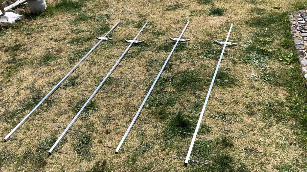
アンテナの組み立て
ブームの干渉具合のチェックを実施するために、とりあえず1本作成しました。
I made one for the time being to check the degree of interference of the boom.
天野アルミニウムから購入した20㎜角のパイプ。板厚はt2なので結構しっかりしています。
A 20mm square pipe purchased from Amano Aluminum. The board thickness is t2, so it is quite solid.
このパイプに計算した長さの位置にマーキングを入れていきます。コンベックスはガタが有るので、曲尺を使っての測定とマーキングになります。
Mark the position of the calculated length on this pipe. Since the convex has backlash, it is measured and marked using a steel square.
マーキング箇所は、エレメントの10箇所と放射器の2箇所、そしてコネクタを固定するブラケットの2箇所となり、全部で14か所のマーキングです。
There are 10 markings on the element, 2 on the radiator, and 2 on the bracket to fix the connector, for a total of 14 markings.
これを4本分について全部行います。
Do this for all four.
エレメントの穴あけ位置に対して、放射器は90度ずれた位置に。更にはコネクタブラケット取り付けは、放射器の反対側とマーキングをする位置がバラバラなので、意外と時間が掛かりました。最初の1本はコネクタブラケットの位置のマーキングを間違えてしまいました。
The radiator is 90 degrees away from the drilling position of the element. Furthermore, installing the connector bracket took a surprising amount of time because the marking position was different from the opposite side of the radiator. The first one made a mistake in marking the position of the connector bracket.
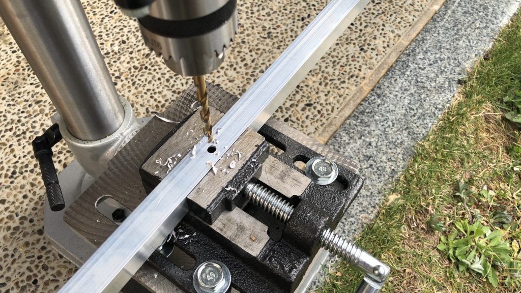
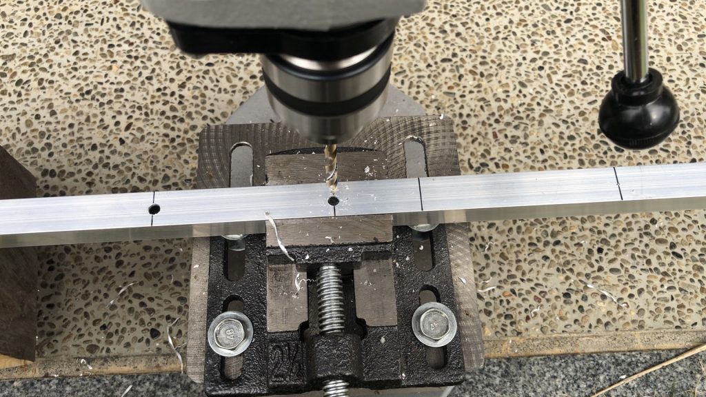
マーキングが完了したら、ポンチで穴あけ位置を更にマークして穴あけ作業の開始です。
After the marking is completed, mark the drilling position further with a punch and start the drilling work.
エレメントがΦ4に対して、エレメント固定用のブッシュがΦ6なので、6㎜の穴を開けます。このブッシュはDG7YBNデザインで押し込むとエレメントが固定される構造のものです。
Since the element is Φ4 and the bush for fixing the element is Φ6, make a hole of 6 mm. This bush has a DG7YBN design with a structure that fixes the element when pushed in.
エレメント用の穴あけが終わったら、今度は放射器とコネクタブラケット用の穴を2.8mmで開けます。
After drilling the holes for the element, it’s time to drill the holes for the radiator and connector bracket at 2.8 mm.
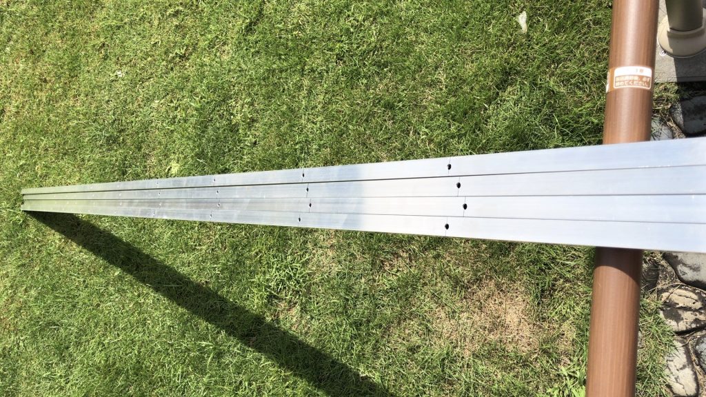
4本分のブーム全てに先に穴あけ工事を完了させます。ここまで完了しておけば、時間がある時に本体組み立てをすればいいだけですからね。
Complete the drilling work for all four booms first. If you complete this, you only have to assemble the main body when you have time.
さて、次はエレメントの取り付けになります。
Now, the next step is to install the element.
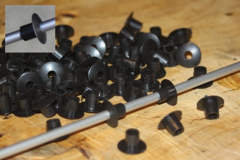
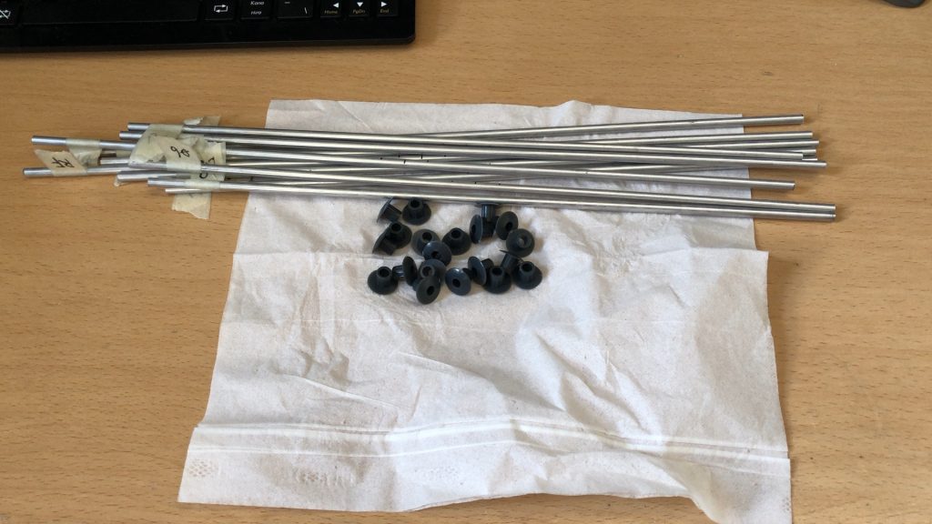
まず放射器以外のエレメントと固定ブッシュで1っセット当たり使用する部品はこれだけです。
First of all, this is the only part used per set of elements other than the radiator and the fixed bush.
このブッシュは優れモノなので、DG7YBNに追加注文を入れようとしたのですが在庫切れで、しかも製造が中国なのでコロナの影響を受けているので、入手は何時になるか未定との事でした。
Since this bush is an excellent product, I tried to place an additional order for DG7YBN, but it was out of stock, and since it was manufactured in China, it was affected by COVID-19, so it was undecided when it would be available.
このブッシュを使えば、M2アンテナのようにブッシュとプッシュロックの組み合わせではないので、部品点数が半分ですみます。
If you use this bush, it is not a combination of bush and push lock like M2 antenna, so the number of parts is halved.
エレメントの取り付け作業は、エレメントにブッシュを通した後に、ブームに押し込むだけで完了です。
To install the element, simply pass the bush through the element and then push it into the boom.
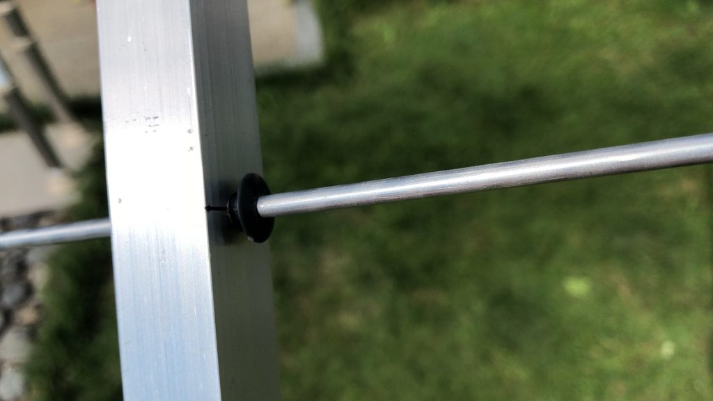
こんな感じでブッシュにエレメントを通し、それをブームに圧入するだけなんです。圧入作業には720のエレメントが丁度良い大きさなので、これを使いハンマーで軽く叩いて押し込みます。
Just pass the element through the bush like this and press it into the boom. The 720 element is just the right size for press-fitting work, so use it and tap it lightly with a hammer to push it in.
圧入が完了するとこんな感じでエレメントが固定されます。
When the press fitting is completed, the element is fixed like this.
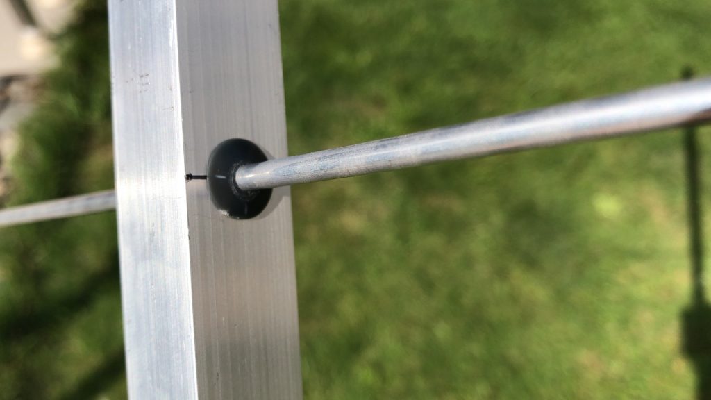
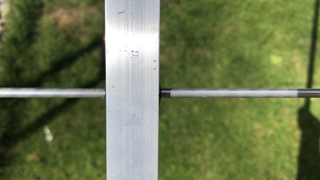
こんな感じで、エレメントブッシュはほとんど分からないですね。ちなみに右側には720のエレメントを挿入して押し込んでいるところです。
With this kind of feeling, you can hardly understand the element bush. By the way, the 720 element is inserted and pushed in on the right side.
放射器を除き、11本のエレメントの挿入が終わればほぼ完成になります。
With the exception of the radiator, it is almost complete when the 11 elements have been inserted.
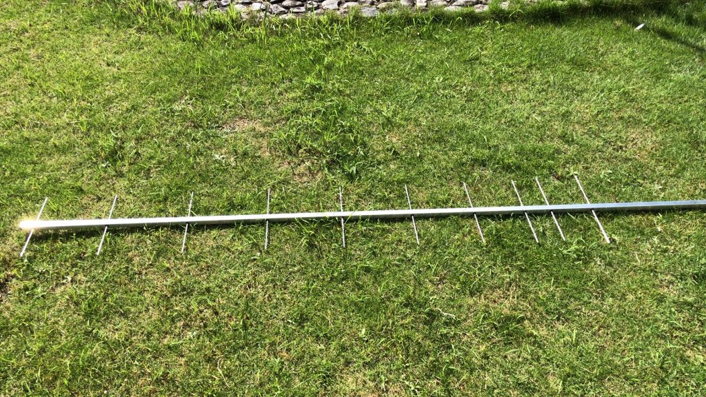
さてここまで来たらもう一息、放射器の取り付けと同軸バランの取り付けで完了になります。
Now that you’ve come this far, it’s time to install the radiator and the coaxial balun.
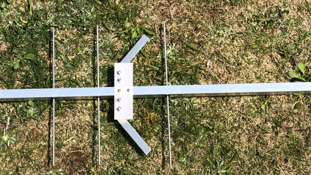
まずは放射器の取り付け
First, install the radiator
同時にマストに固定するクロスマウントも取り付けました。
At the same time, I also attached a cross mount to fix it to the mast.
同軸バランを取り付けてこれで完成になります。
Attach the coaxial balun and you’re done.
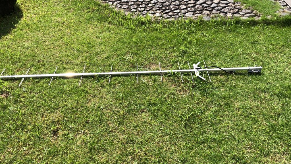
この完成品を手持ちのマストに取り付けて、マストとアンテナの干渉確認を実施しました。特に影響もなく432MHzでのSWRは1.0でインピーダンスもほぼ50Ωでした。一様設計通りになっていますね。
I attached this finished product to my mast and checked the interference between the mast and the antenna. The SWR at 432MHz was 1.0 and the impedance was almost 50Ω without any particular effect. It’s exactly as designed.
後は4パラx2にした時にどうなるかだけです。
The only thing left is what happens when you make 4 para x2.
4パラ2段用の専用マストの作成。
一般的にはスタック2段にする場合、エ型のマストで取り付けると思いますが、今回は既にあるクロスマウントを活用するためにH型のマストにします。
Generally, when stacking two stages, I think that it is attached with an H-shaped mast tilted 90 degrees, but this time I will use an H-shaped mast to utilize the existing cross mount.
そのため、1本先に作ってマストの影響の確認を実施したんです。
Therefore, I made one first and checked the influence of the mast.
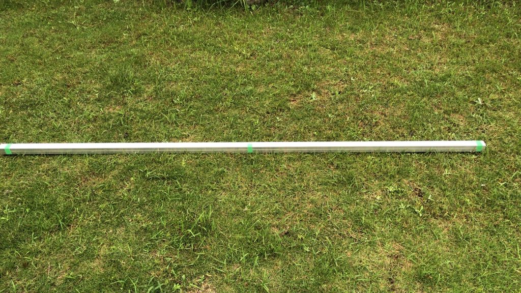
いつも通りアルミパイプは天野アルミニウムさんからの購入。
As usual, the aluminum pipe was purchased from Amano Aluminum.
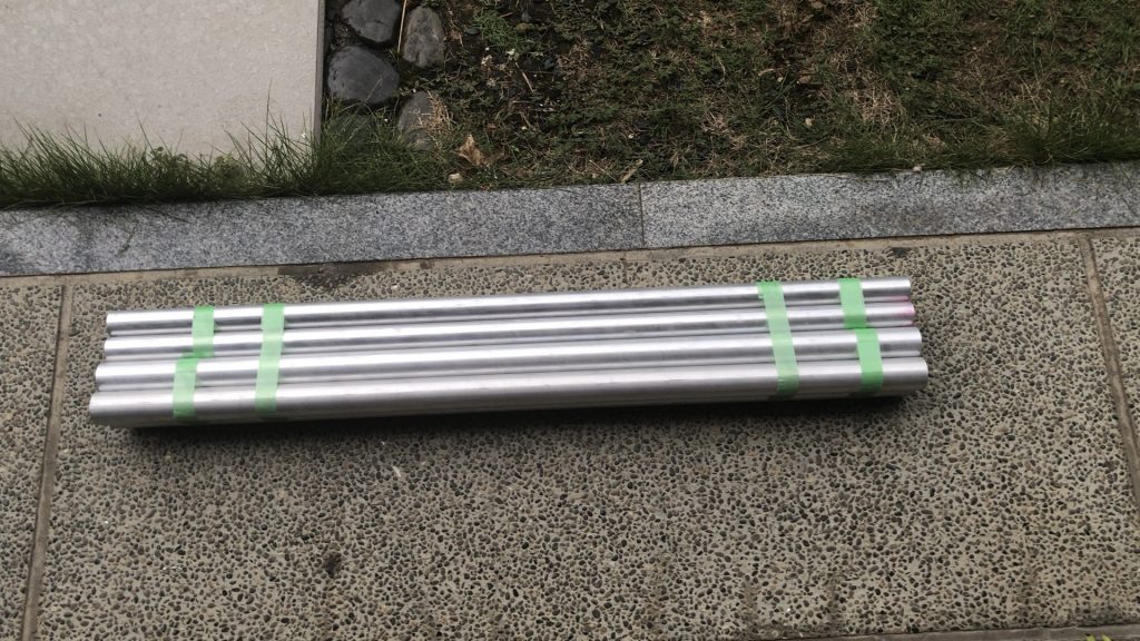
送られてきたアルミパイプは40㎜と35㎜の2種類が4本です。40㎜の中に35㎜を入れて2重化する計画です。
There are four types of aluminum pipes sent, 40 mm and 35 mm. We plan to put 35 mm in 40 mm and double it.
実際の厚みを見てみると、板厚2㎜って結構厚い感じがします。HFのアンテナなんかこれくらいの厚み使ってるんじゃないかな。
Looking at the actual thickness, it feels quite thick with a plate thickness of 2 mm. I think the HF antenna is about this thick.
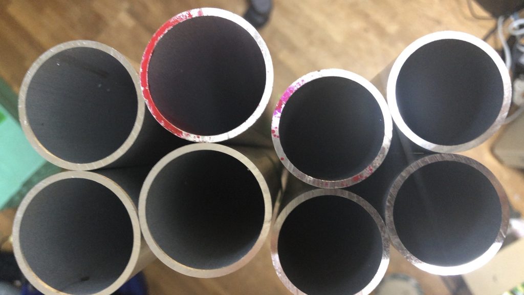
しかしマストとして使用し、しかも先端には2.5mの偏重心のアンテナが取り付けられて風に振られても大丈夫なように、安全を見て2重にします。板厚4㎜って結構厚くなりますね。
However, it is used as a mast, and a 2.5m eccentric center of gravity antenna is attached to the tip so that it can be shaken by the wind, so it is doubled for safety. The board thickness is 4 mm, which makes it quite thick.
室内で作業したので、切り屑が飛び散らないようにガムテープを使って保護。リベット用の下穴を開けてリベットで取り付けです。
Since I worked indoors, I used gum tape to protect the chips from scattering. It is attached with rivets by making a pilot hole for rivets.
板厚が4㎜になるので、リベットも勢いよく締め上げると割れてしまうので、じわりじわりと力をかけて締め上げていきます。
Since the plate thickness is 4 mm, the rivets will crack if tightened vigorously, so gradually tighten them with force.
上下に90度ずらしで全部で4ヶ所のリベットを打ち完成させました。板厚4㎜ってこんな感じの厚さになり、重量もぐっと増えました。さすがにこの厚さになると簡単には曲がらないと思います。
A total of 4 rivets were struck and completed by shifting 90 degrees up and down. The thickness of the board is 4 mm, which is like this, and the weight has increased dramatically. I don’t think it will bend easily at this thickness.
賞味作業時間は1.5時間程度でした。
The actual working time was about 1.5 hours.
最終部品入手からアンテナ組立へ
GTV70-11wのシステムアップに使用する最終部品である分配器を本日入手した。自分で作っても良いのだが、測定器が少なく同じ精度のものが4つ作れるか自信も無かったので、市販品を購入してコストと時間を効率化した。
I got the distributor, which is the final part used to upgrade the system of GTV70-11w, today. I could make it myself, but I wasn’t sure if I could make four of them with the same accuracy because there were few measuring instruments, so I bought a commercial product to save cost and time.
70㎝バンド用の分配器なのだが、中に分配用の同軸が2本入っているために大そう大きな箱になってしまっている。
It’s a distributor for 70 cm band, but it’s a big box because it contains two coaxial cables for distribution.
1箱の中身は分配器1個と10D-FBの分配用同軸が2本、分配器をマストに止める結束バンドの3つだ。
The contents of one box are one distributor, two coaxial cables for distribution of 10D-FB, and three binding bands that fasten the distributor to the mast.
さあ到着したからと思ったのだが、あいにくの雨模様になってしまい明日もぐずついた天気ようなので、しばらくはお預け状態。
I thought it was because I arrived, but unfortunately it was raining and the weather seemed to be gloomy tomorrow, so I left it for a while.
これでいよいよGTV70-11wが4x2にグレードアップ、シミュレーション上では
With this, GTV70-11w is finally upgraded to 4×2, in the simulation
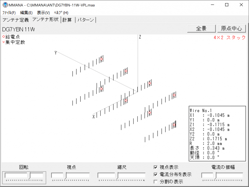
こんな形になって、ビームパターンはこうなる予定。
The beam pattern will be like this.
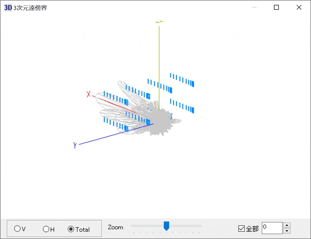
こうなることを期待しているのだがどうかな。
I’m hoping this will happen.
翌日、そしてアンテナ組立は最終段階に入りました。
The next day, and antenna assembly was in the final stages.
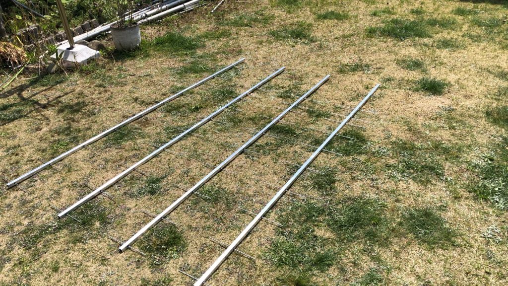
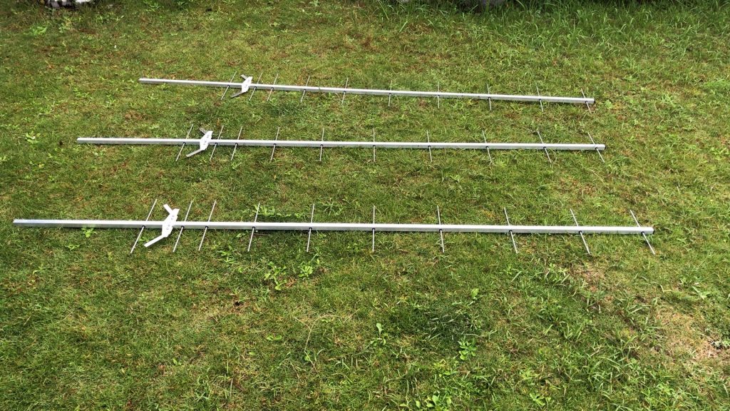
まずはアンテナまでを完成させました。すでに1本は完成していますので、残りの3本の組み立て作業です。
First of all, I completed the antenna. Since one has already been completed, it is time to assemble the remaining three.
まずはこの前完成した部分までを庭に出して、事前に作成をしておいた放射器の取り付け作業を行います。取り付けはビス2本での固定になります。
First of all, we will put out the completed part to the garden and install the radiator that was created in advance. Installation is fixed with two screws.
ここまでは簡単な作業なので直ぐに終わりました。
This is a simple task, so it was finished immediately.
そして最後は同軸バランの取り付けと、コネクタの固定、分配器用同軸の取り付けになります。
And finally, the installation of the coaxial balun, the fixing of the connector, and the installation of the coaxial for the distributor.
コネクタ固定金具が意外とめんどくさいのですね。また、分配器用同軸が10D-FBなので取りましがめんどくさい感じです。
The connector fixing bracket is surprisingly annoying, isn’t it? Also, since the coaxial for the distributor is 10D-FB, it feels awkward to handle.
たったこれだけでも1時間半の時間を要しました。今回は、ちゃんとコネクタの固定位置まで考えているので、前回の時とは大違いにみてくれもカッコいいですね。
This alone took an hour and a half. This time, I’m thinking about the fixed position of the connector properly, so it’s cool to see it as a big difference from the last time.
最終的には、マストに取り付けるクロスマウントを取り付けて分配器用の同軸もテープで固定しました。最終的には結束バンドで固定しますが凡その位置と言う目印もかねてです。
Finally, I attached a cross mount to the mast and taped the coax for the distributor. In the end, it is fixed with a cable tie, but it also serves as a mark of the approximate position.
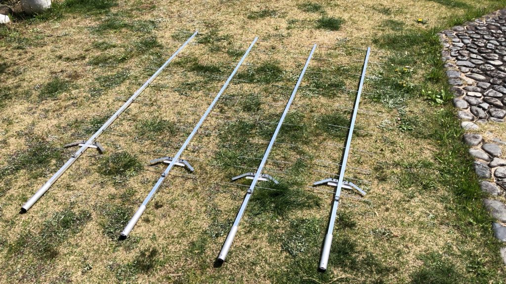
これで4組のアンテナが出来上がりました。後は現状上がっている4本と組み合わせるだけですね。
This completes 4 sets of antennas. The rest is just to combine it with the four that are currently up.
これでGTV70-11w x 4 が GTV70-11w x 4 x 2 の8八木にグレードアップします。
This will upgrade GTV70-11w x 4 to GTV70-11w x 4 x 2 for 8Yagi.
いよいよ、合体作業になります。現状のアンテナを固定しているクロスマウントを使用してマストを取り付けます。
It’s finally time to combine. Install the mast using the cross mount that holds the current antenna in place.
そのために、現有アンテナを取り外して最新状態に改造するため一旦降ろしたりして作業を行いました。
For that reason, I removed the existing antenna and took it down to remodel it to the latest state.
途中で、Uボルト2本ねじ切ってしまいました。ステンレス製のUボルトは、高速で絞めたり緩めたりすると、摩擦熱で焼き付きが発生してねじ切れてしまいますね。
On the way, I screwed two U bolts. If you tighten or loosen a stainless steel U-bolt at high speed, frictional heat will cause seizure and the screw will break.
他のアンテナのクロスマウントを使い回していたので、何回もしめたり緩めたりをくりかえしていたので、その結果なんでしょうね。
I used to use the cross mounts of other antennas, so I had to tighten and loosen them many times, which is probably the result.
ブーム上には分配器だらけになり、ケーブルフォーミングに時間がかかってしまい、できた時には日没ギリギリ。危うく日没サスペンデットになる手前でした。
The boom was full of distributors, and cable forming took a long time, and when it was possible, it was just before sunset. It was almost before the sunset suspend.
一番気になるのは、単体でチェックしたときはSWRが432.1MHzで1.0でしたが、実際にアレイ化してみた時に周囲の影響が出ていないかが心配になりました。
The most worrisome thing was that the SWR was 1.0 at 432.1MHz when I checked it alone, but when I actually tried to array it, I was worried that there was no influence from the surroundings.
まずはGTV70-11w x 8のSWRチェックは、432.1MHzで単品と同じ1.0でした。一安心ですね。
First of all, the SWR check of GTV70-11w x 8 was 1.0, which is the same as the single item at 432.1MHz. It’s a relief.
従来の水平偏波用720 x 8の影響はどうか同じように確認。こちらもSWRは1.0でしたので問題ありません。
Check the effect of the conventional 720 x 8 for horizontal polarization in the same way. Again, the SWR was 1.0, so there is no problem.
かなりトップヘビーな状況になりました。昨年の台風ではマストがロテータークランプの所で若干滑っており、最近気が付いたのですが15度くらい方位がずれていました。
It’s a pretty top heavy situation. In last year’s typhoon, the mast slipped slightly at the rotator clamp, and I recently noticed that it was off by about 15 degrees.
コントローラー側で補正を掛けましたが、一度正規の位置に合わせなおす必要が有るかと思います。
I applied the correction on the controller side, but I think it is necessary to adjust it to the regular position once.
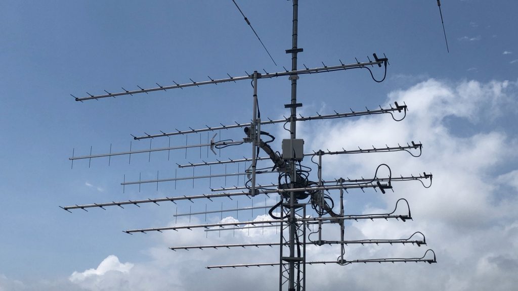
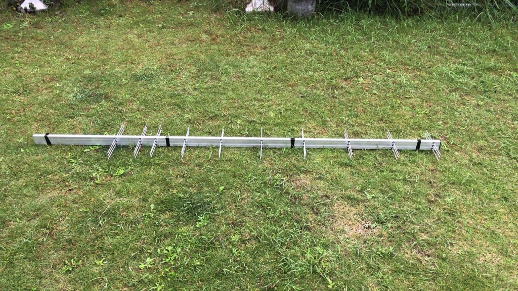
こちらができ上ったアンテナの写真になります。
Here is a picture of the completed antenna.
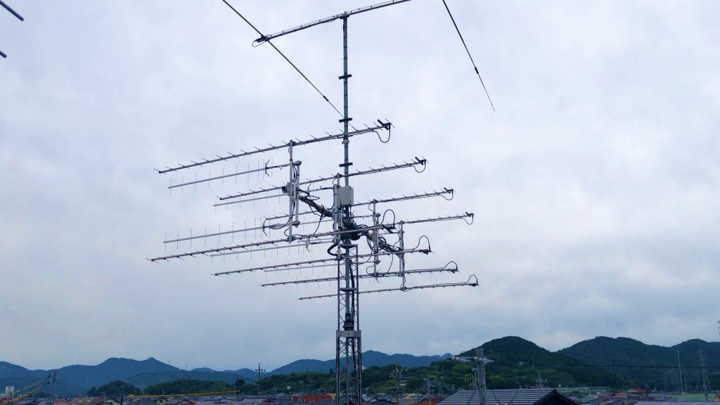
エレメント数が少ない分、スタック間隔が小さくなりますので水平偏波のスタック内に入れ込むように設置しました。
Since the stack spacing becomes smaller as the number of elements decreases, we installed it so that it fits in the horizontally polarized stack.
1個数万する特注のクロスマウントを惜しげもなくいっぱい使ってしまいました。
I have generously used a lot of custom-made cross mounts.
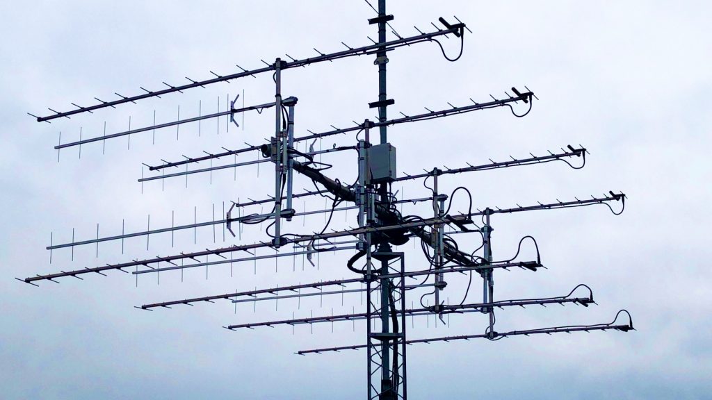
アンテナ自体が片支持のアンテナですので、フロント側を若干持ち上げております。風で振られてもお辞儀はしないと思いますが。
Since the antenna itself is a one-sided support antenna, the front side is slightly raised. I don’t think I’ll bow even if it’s shaken by the wind.
これでGTV70-11wの8八木化作業は完了しました。
This completes the 8 Yagi conversion work for GTV70-11w.


